CHEM 548: Materials Chemistry
Lecture 6: Networks, Silicates, and Microporous Solids
Reading: Woodward, Karen, Evans, and Vogt, Solid State Materials Chemistry
Ch. 1 §§1.4.3–1.4.4, §§1.5.4–1.5.5; Ch. 14 §14.4
Learning Objectives for Networks
- Understand how coordination numbers lead to network topologies in crystal structures.
- Define key terms: vertex (linking point) and linker/edge (connection between vertices).
- Recognize that linkers can be bonds, atoms, or polyatomic groups (e.g., O in zeolites, CN− in Prussian blue, dicarboxylates in MOFs).
- Distinguish between:
- Uninodal nets (all vertices equivalent).
- Binodal nets (two different kinds of vertices).
- Regular nets (all vertices, edges, and angles equivalent).
- Apply network ideas to both simple binary compounds and framework materials (zeolites, MOFs).
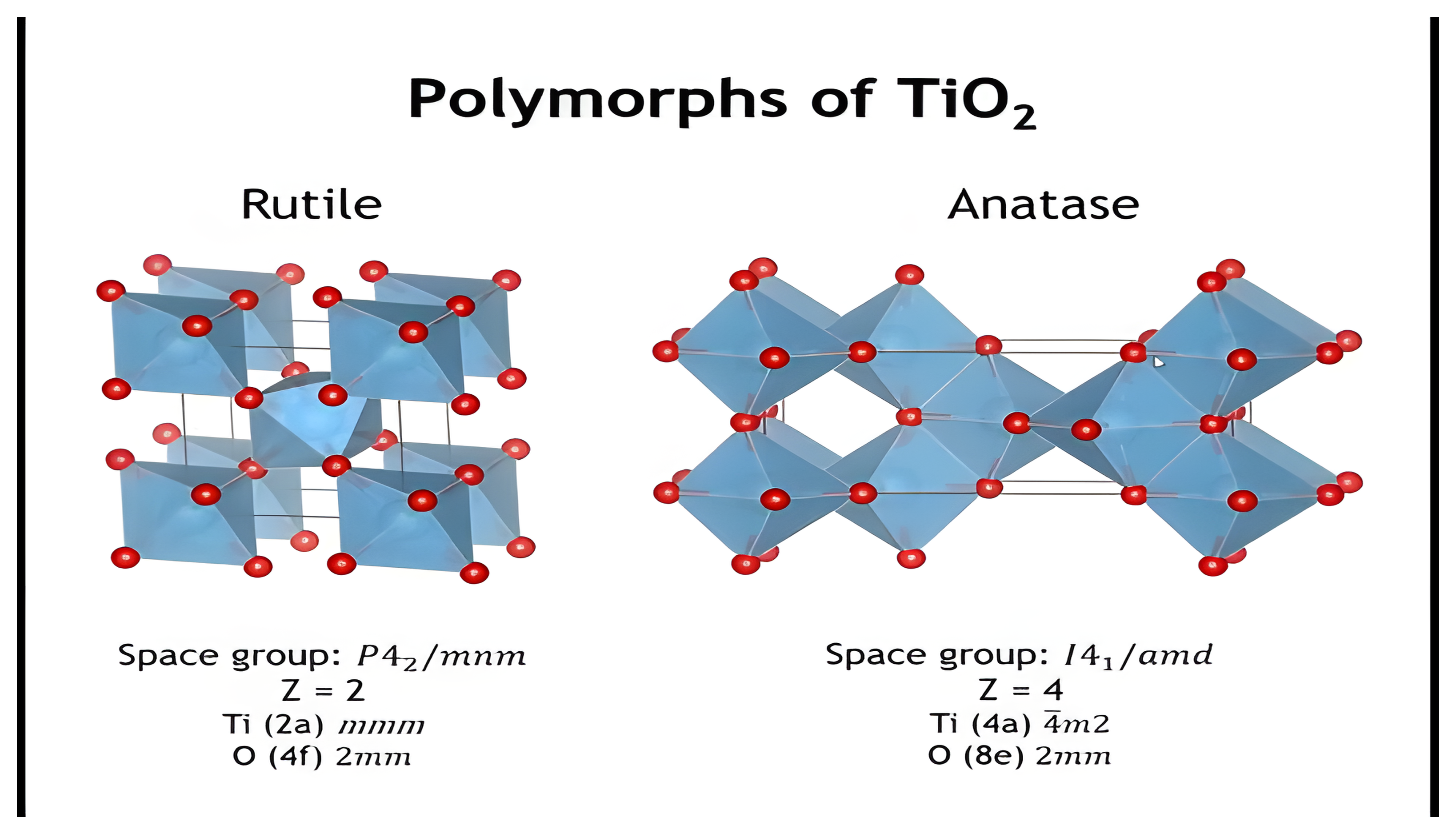
- Relate real crystal structures (e.g., TiO₂ as a 6–3 binodal net) to their underlying network topology.
Network Vocabulary
Vertex = Linking point (in our discussion the vertex will be generally be an atom, though in some cases it will be a cluster of atoms)
Linker = Connects vertices, can take various forms
- A bond, such as in diamond
- Atom, such as the oxygen atoms in a zeolite/silicate
- Molecule, such as a dicarboxylic acid in a MOF
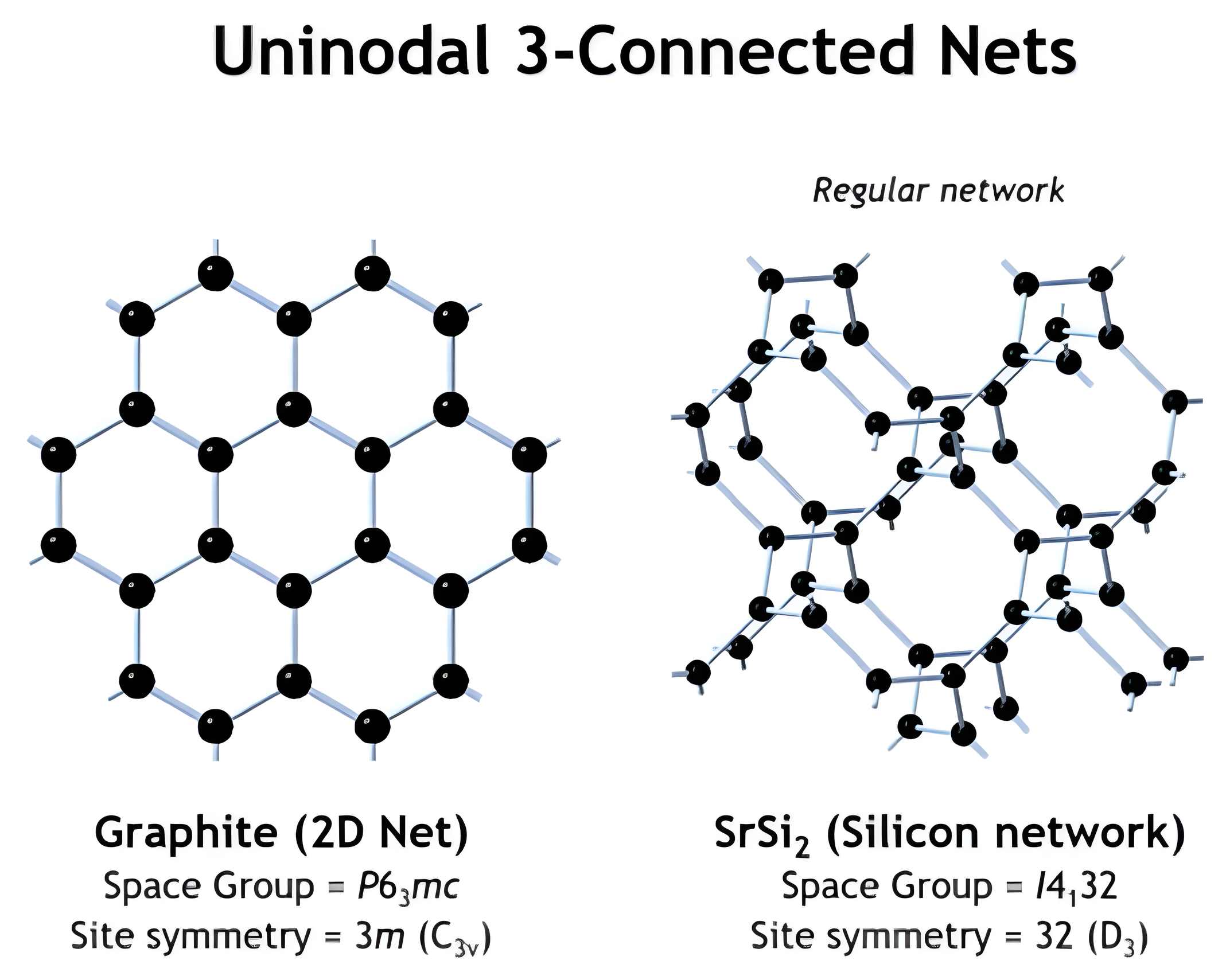
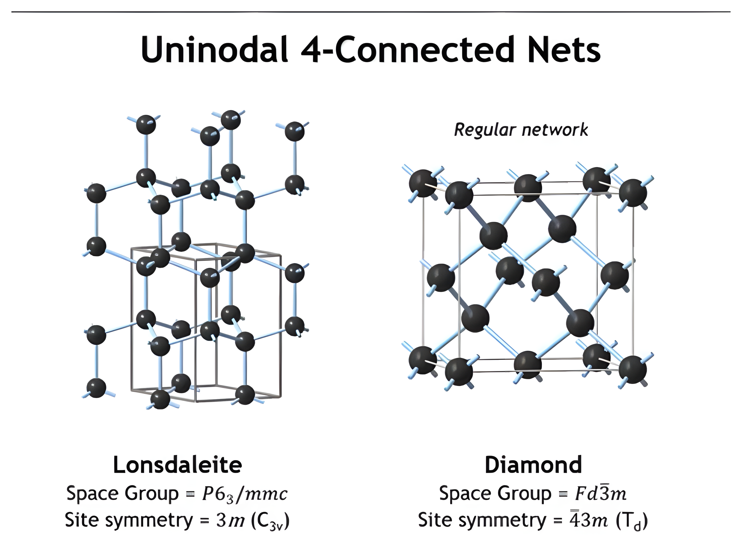
Uninodal Network = All vertices are the same
Binodal Network = Two types of vertices. We use the symbolism (N,M) connected net. For example, TiO₂ is a (6,3) net.
Regular Network = All vertices, edges and angles are equivalent by symmetry
See: M. O’Keeffe, M. Eddauodi, H. Li, T. Reinke & O.M. Yaghi, J. Solid State Chem. 152, 3-20 (2000).
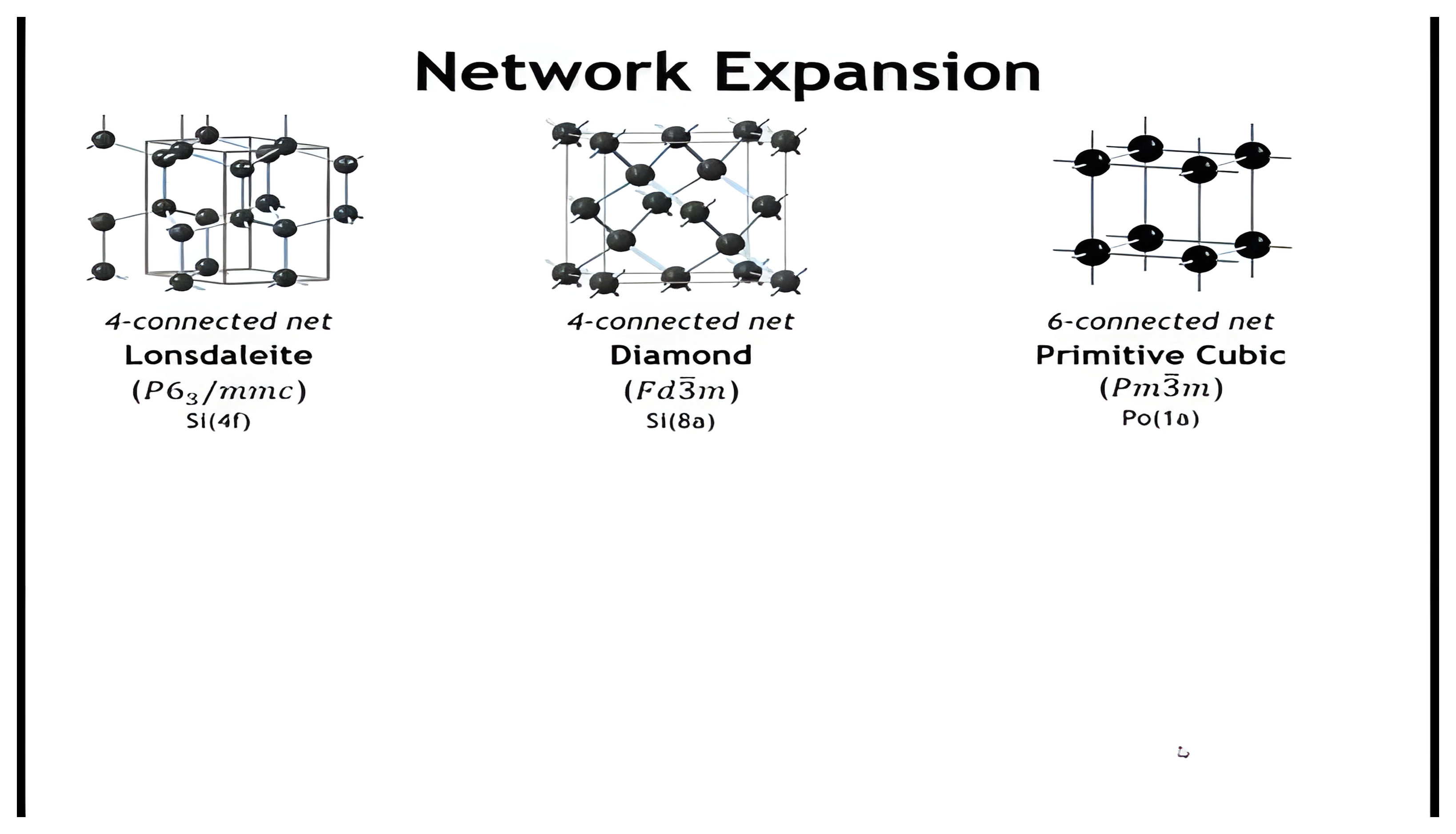
Uninodal 6- and 8-Connected Nets
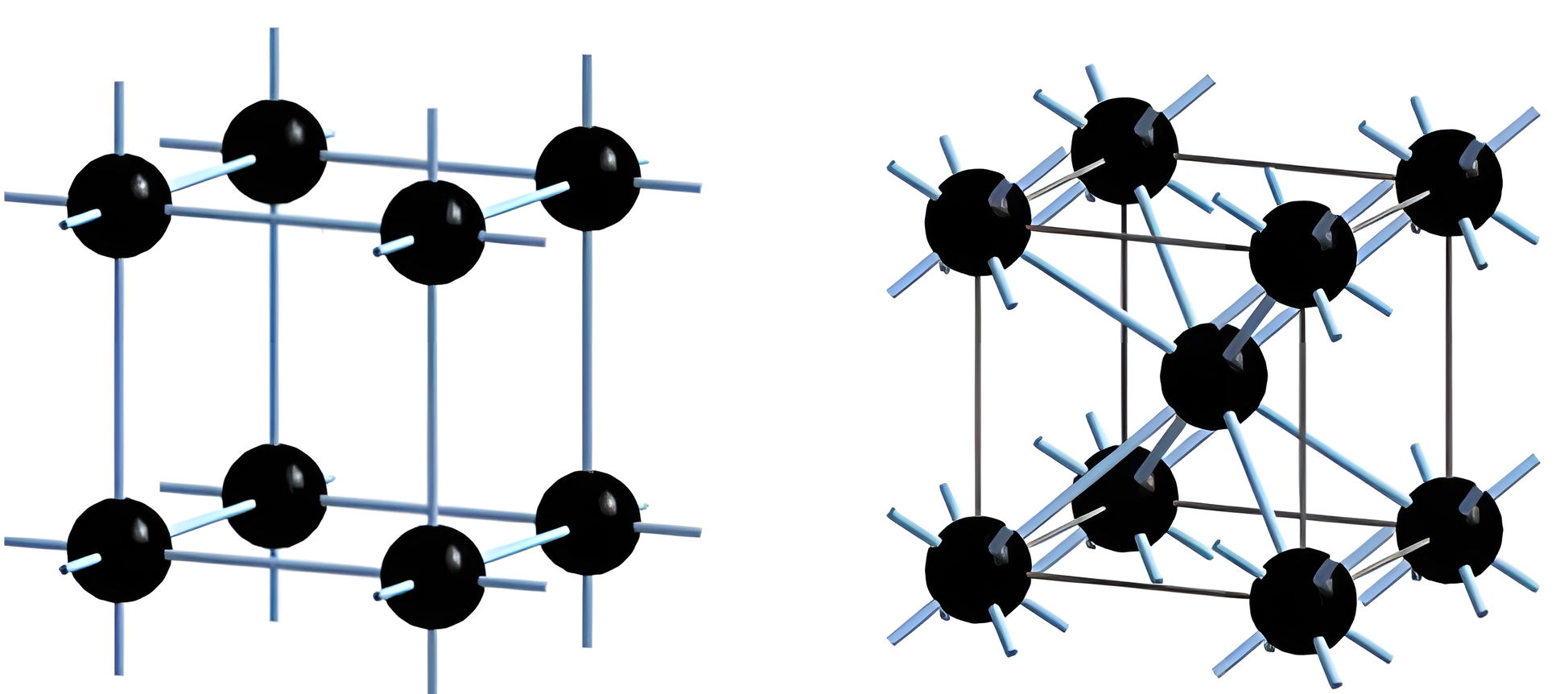
| Regular network | Regular network |
| Primitive cubic (Po) | Body-centered cubic (Fe) |
| Space Group = Pm3̅m | Space Group = Im3̅m |
| Site symmetry = m3̅m (Oh) | Site symmetry = m3̅m (Oh) |
Some Important Binodal Nets
| (N,M)-Net | Coordination Figures | Net (Example) | |
|---|---|---|---|
| 4,2 | Tetrahedron | Linear (bent) | SiO₂ (cristobalite, tridymite) |
| 4,3 | Tetrahedron | Triangle | Si₃N₄ |
| 4,4 | Tetrahedron | Tetrahedron | ZnS (sphalerite, wurtzite) |
| 4,3 | Square | Triangle | Pt₃O₄ |
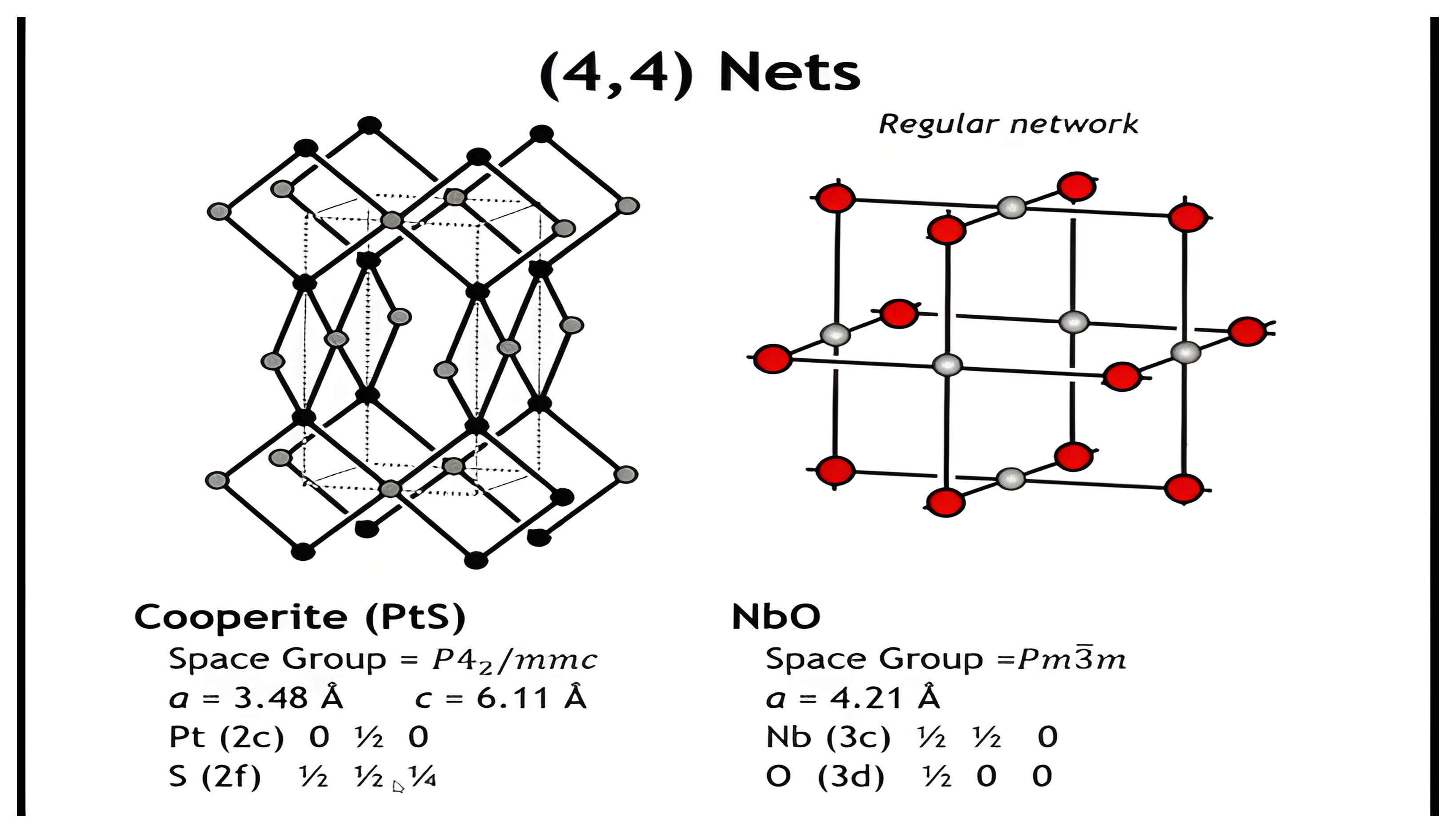
| 4,4 | Square | Square | NbO |
| 4,4 | Square | Tetrahedron | Cooperite (PtS) |
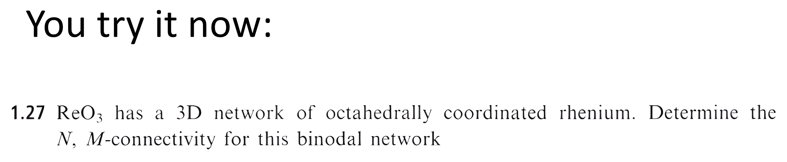
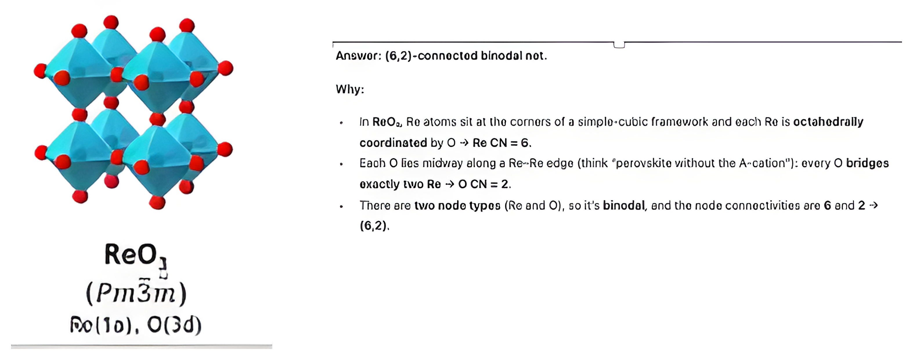
| 6,2 | Octahedron | Linear | ReO₃ |
| 6,3 | Octahedron | Triangle | TiO₂ (rutile, anatase) |
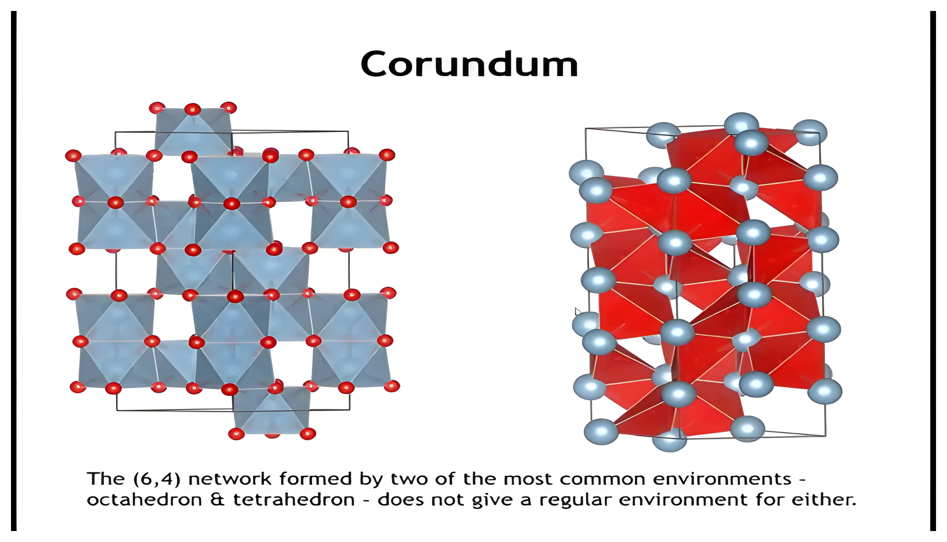
| 6,4 | Octahedron | Tetrahedron | Corundum (Al₂O₃) |
| 6,6 | Octahedron | Octahedron | Rock salt (NaCl) |
| 6,6 | Octahedron | Trigonal prism | NiAs |
| 8,4 | Cube | Tetrahedron | Fluorite (CaF₂) |
| 8,8 | Cube | Cube | CsCl |
Summary for Networks
- Networks describe how atoms connect, abstracted into vertices and linkers.
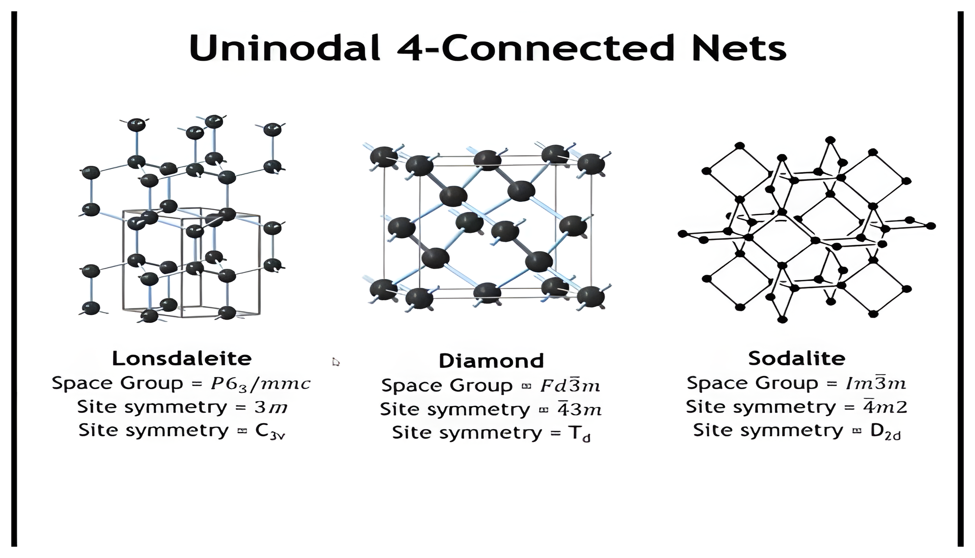
- Uninodal nets: all vertices identical (e.g., diamond, graphite, cubic/bcc nets).
- Binodal nets: two vertex types with different coordination (e.g., Ti 6–O 3 in TiO₂).
- Regular nets: rare, highly symmetric cases where all vertices, edges, and angles are equivalent.
- Transformations of nets:
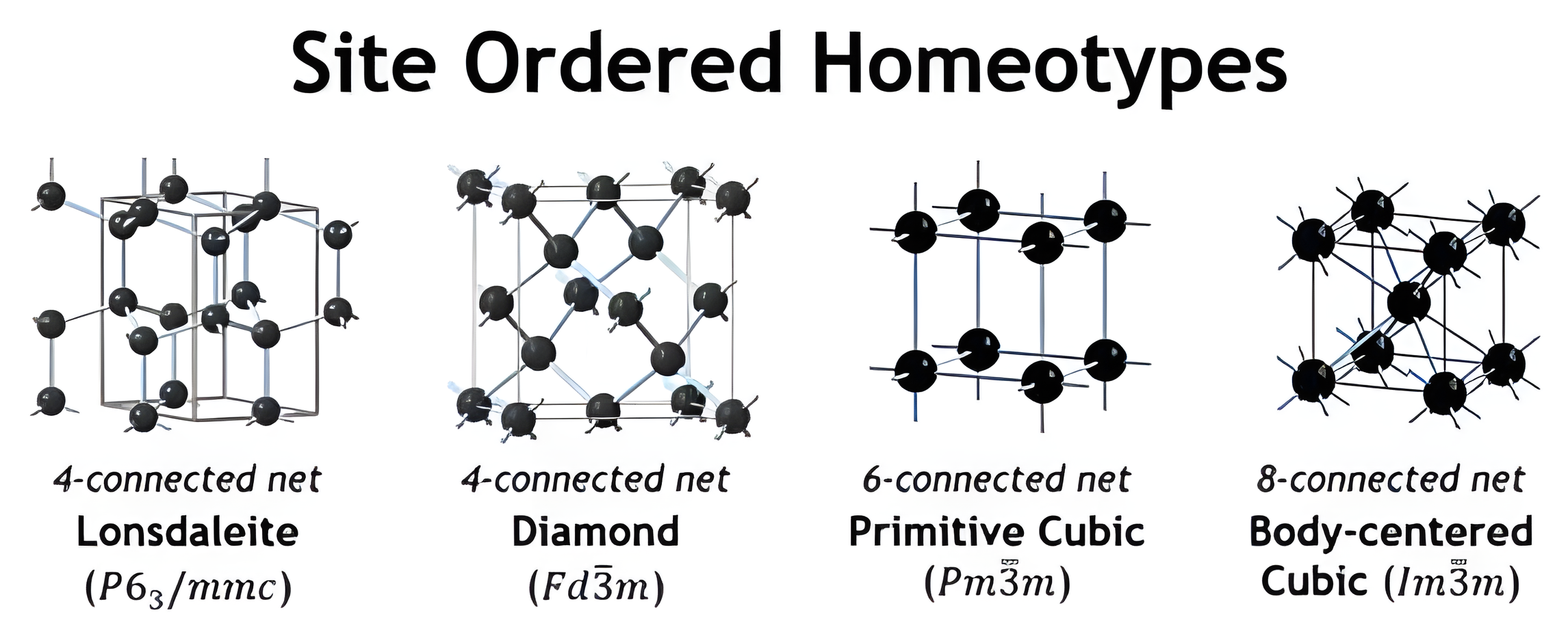
- Site ordering → compounds like NaCl, CsCl, sphalerite, wurtzite.
- Network expansion → insert atoms as linkers (e.g., ReO₃, perovskite).
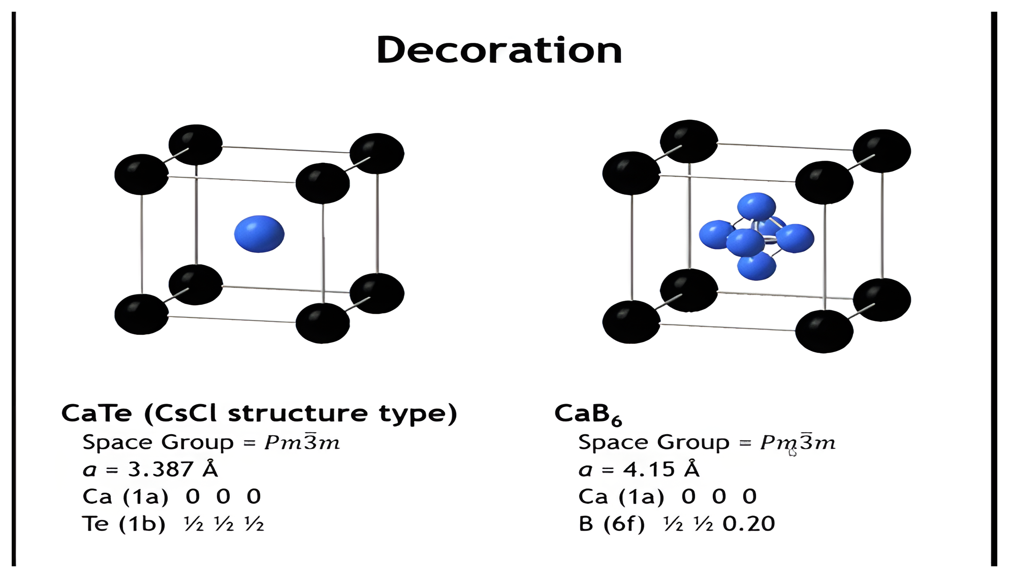
- Decoration → replace simple vertices with polyatomic clusters (e.g., CaB₆).
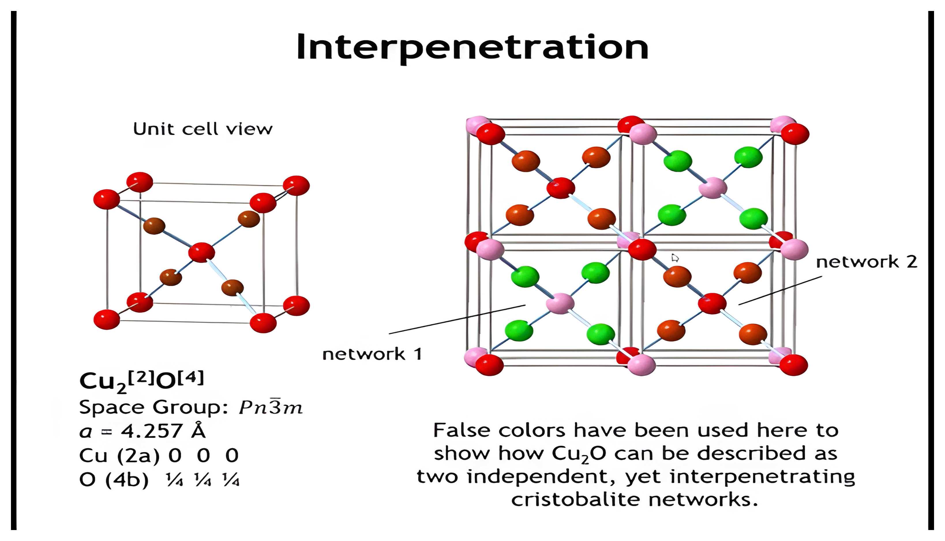
- Interpenetration → overlapping nets (e.g., Cu₂O).
- Binodal nets provide a systematic way to connect empirical formulas, coordination numbers, and real crystal structures.
Silicates and Microporous Solids
Learning Objectives
By the end of this lecture, you should be able to:
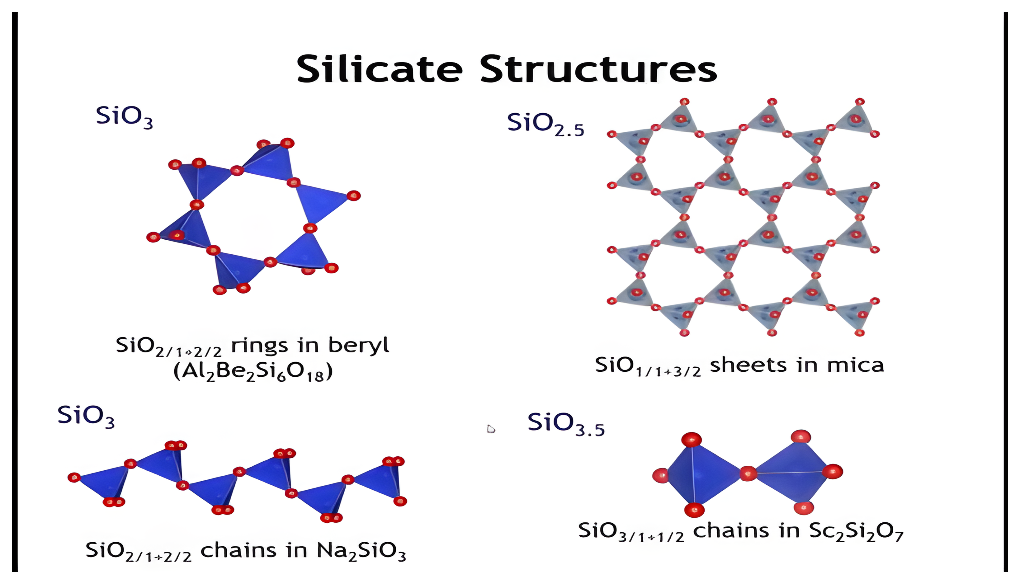
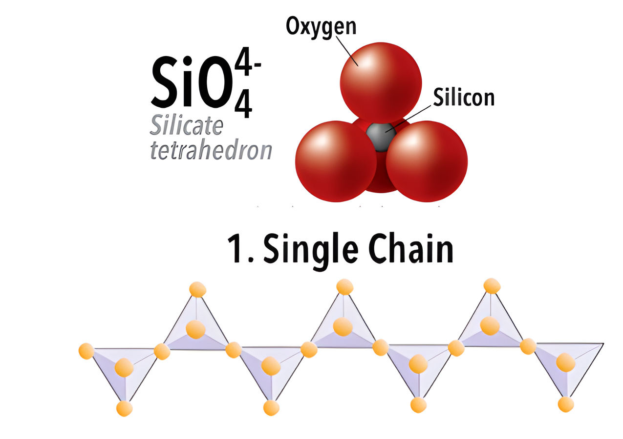
- Explain how silicate structures are built from corner-sharing SiO₄ tetrahedra.
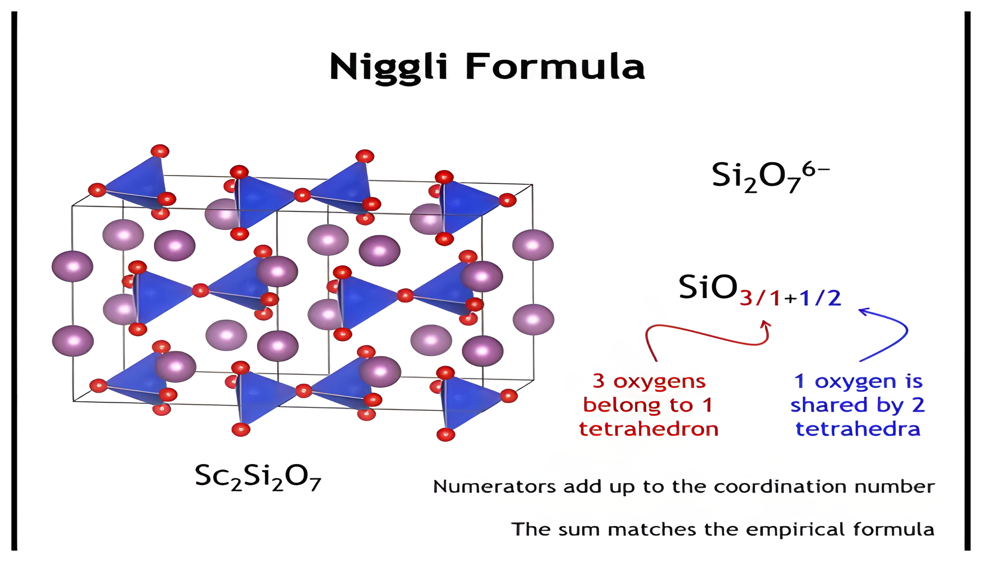
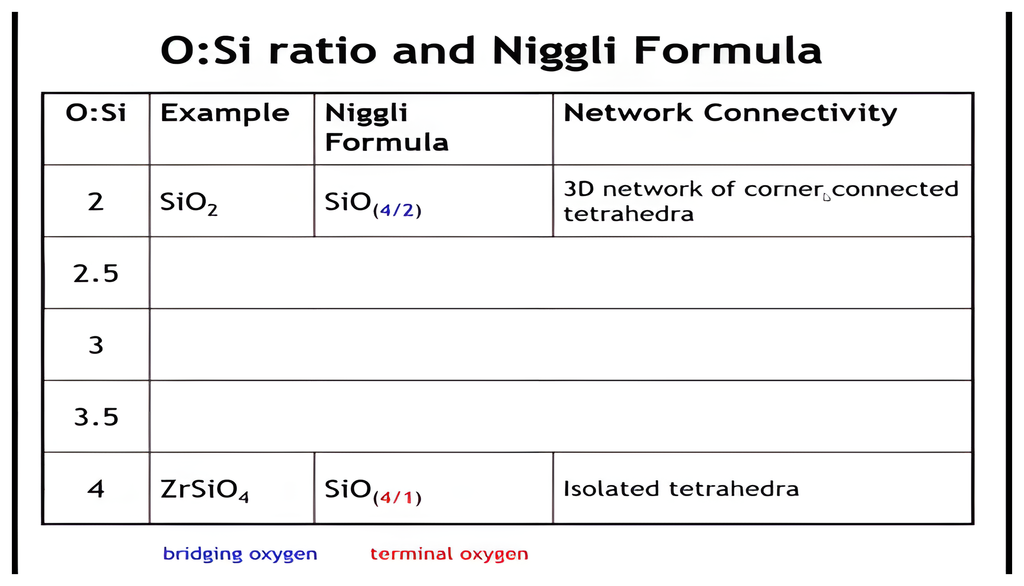
- Use the Niggli formula to relate oxygen: silicon ratios to structural motifs.
- Identify structural motifs (isolated tetrahedra, chains, rings, sheets, frameworks) from O:Si ratios.
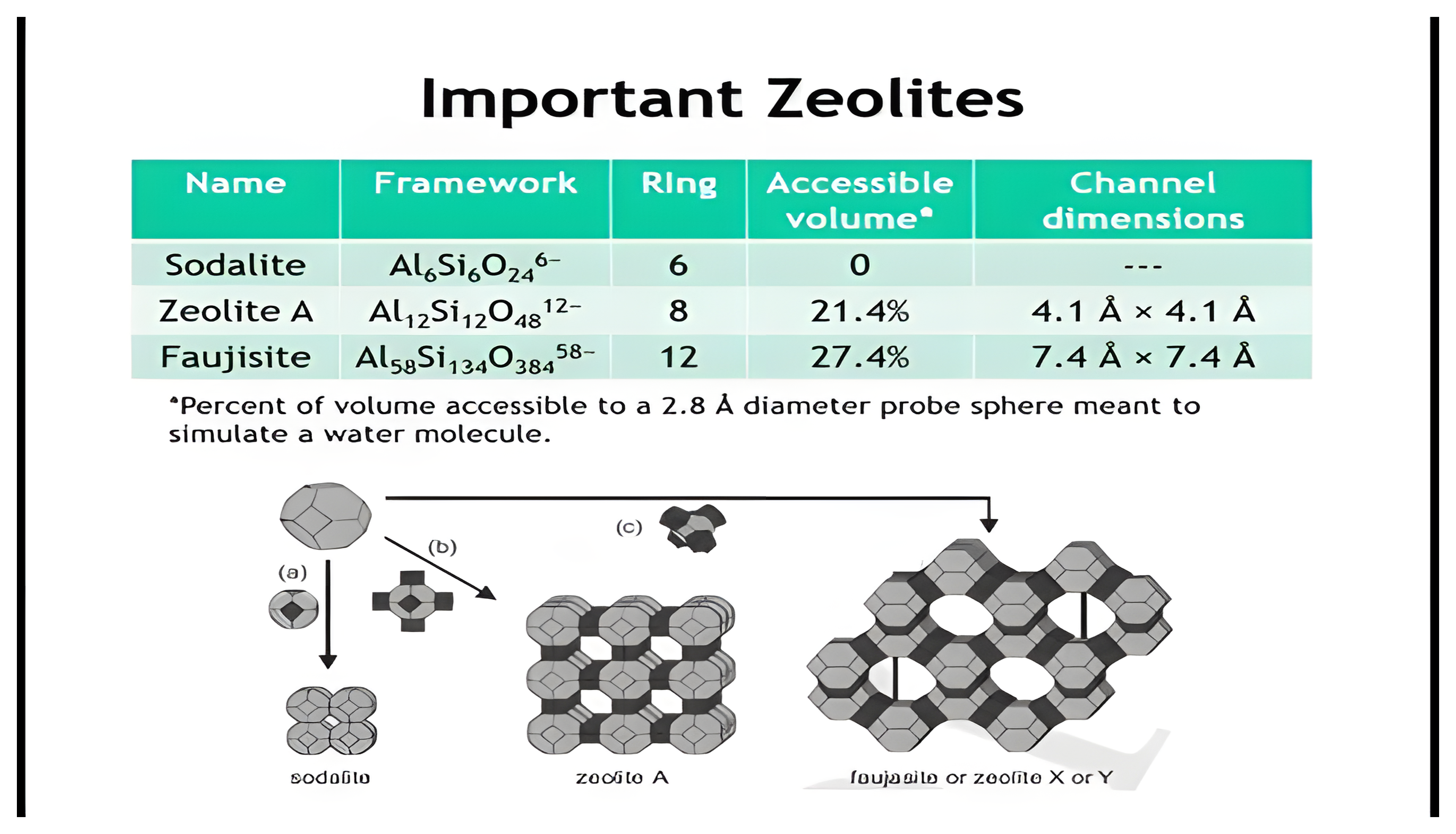
- Describe how zeolites form from Al/Si tetrahedra and why cations create porosity.
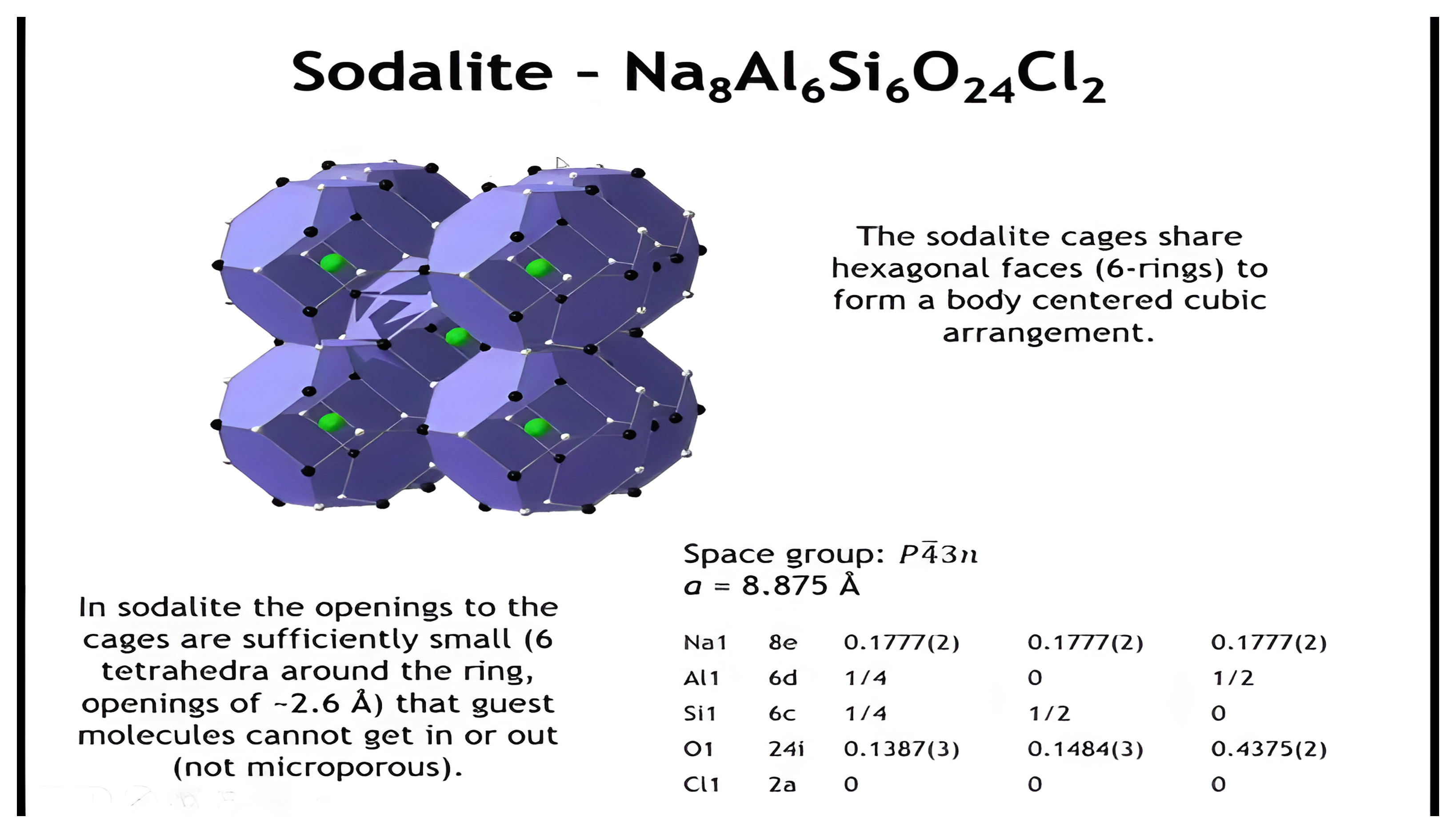
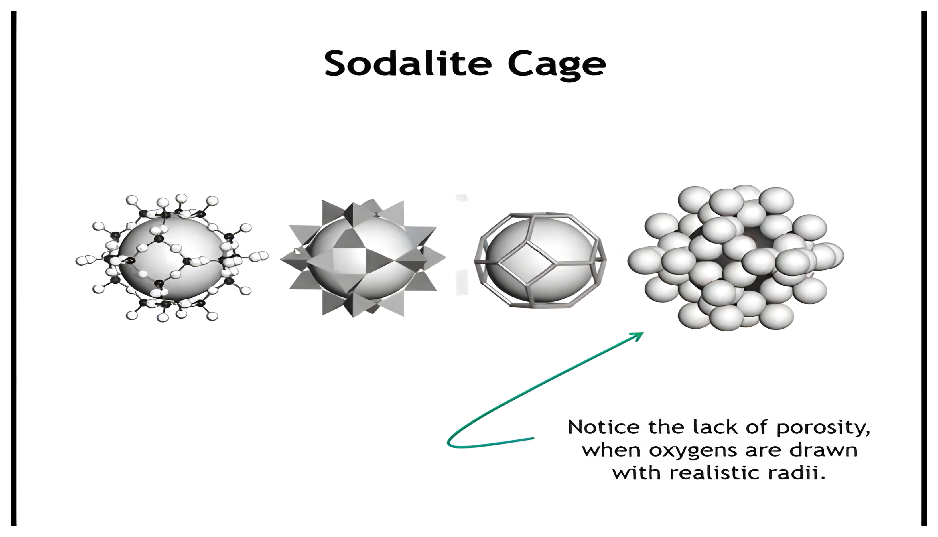
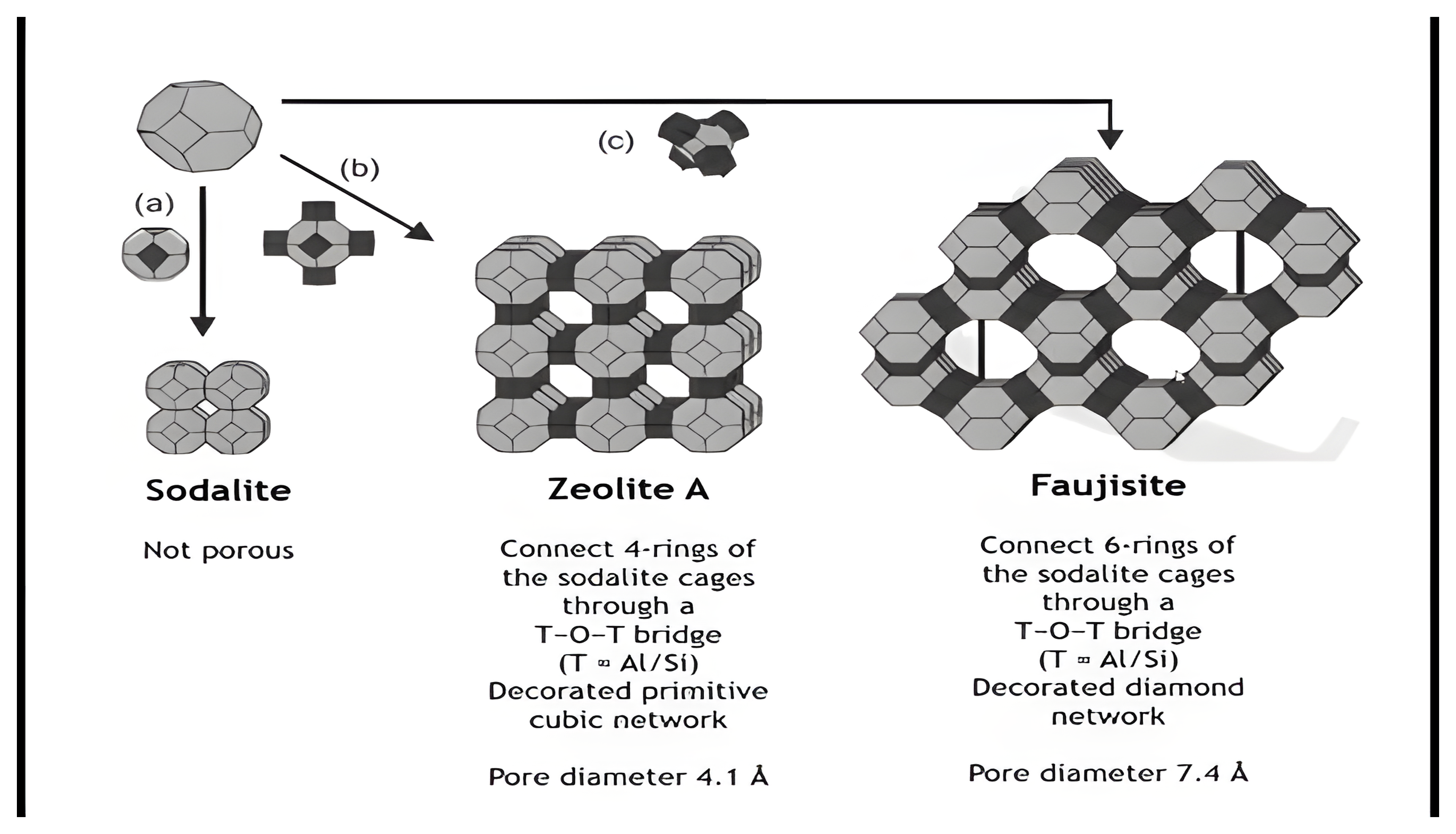
- Recognize key zeolite building blocks (sodalite cage, zeolite A, faujasite) and their pore sizes.
- Distinguish microporous, mesoporous, and macroporous solids.
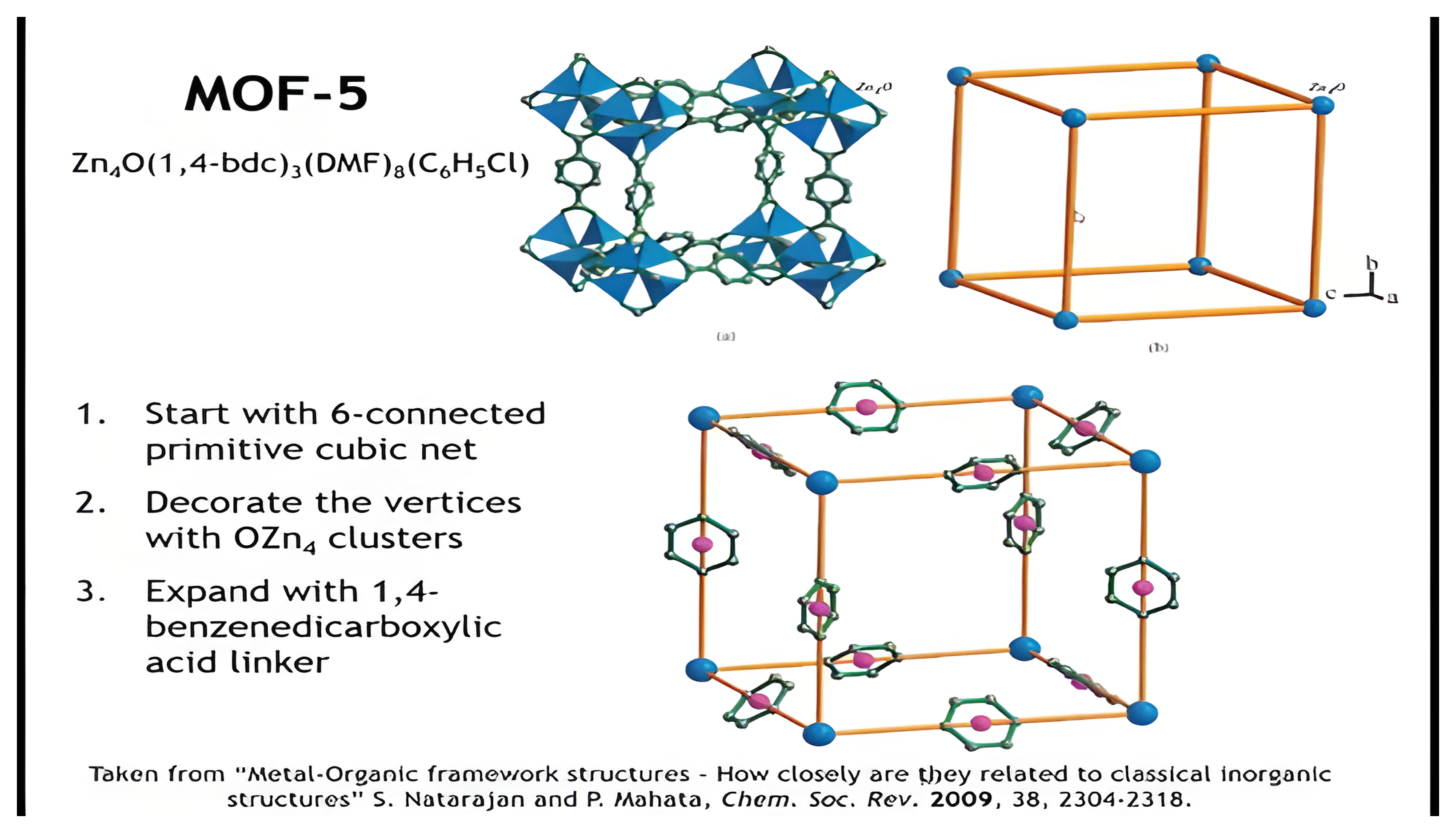
- Understand the basics of MOFs and how MOF-5 is constructed from nets.
Silicates
- Silicates are the most common minerals in the earth’s crust
- Silicates represent about one third of known inorganic crystal structure types
- Silicates generally share a number of common features
- Tetrahedrally coordinated silicon
- If connected tetrahedra are connected through corner sharing
- The O:Si ratio is an important parameter in dictating the extent to which the tetrahedra are connected
Porous Materials
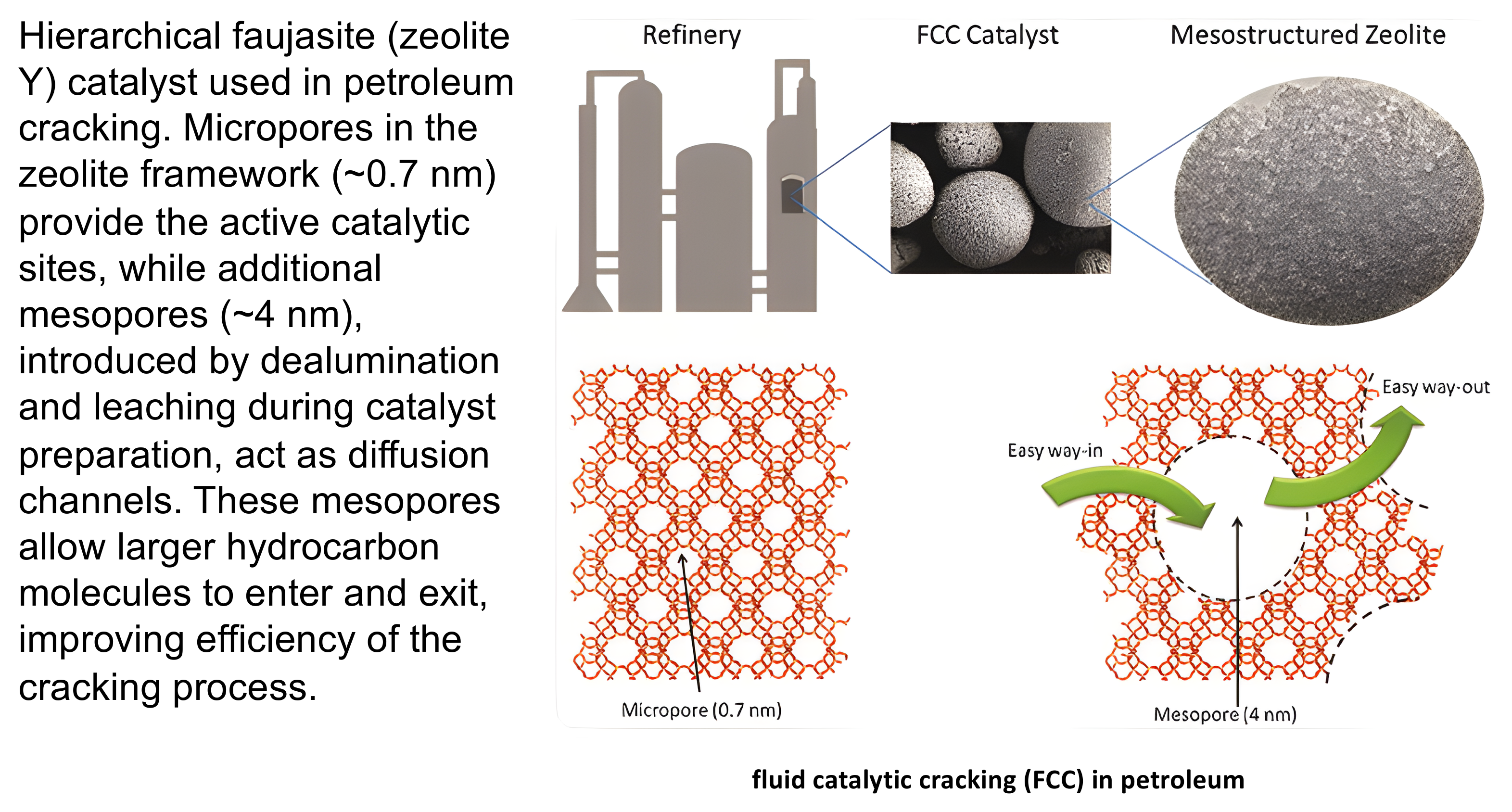
Zeolites (Boiling stone) = Framework materials built from corner connected SiO₄/₂ and AlO₄/₂ tetrahedra
Zeotypes = Similar to zeolites but with other elements on the tetrahedral sites
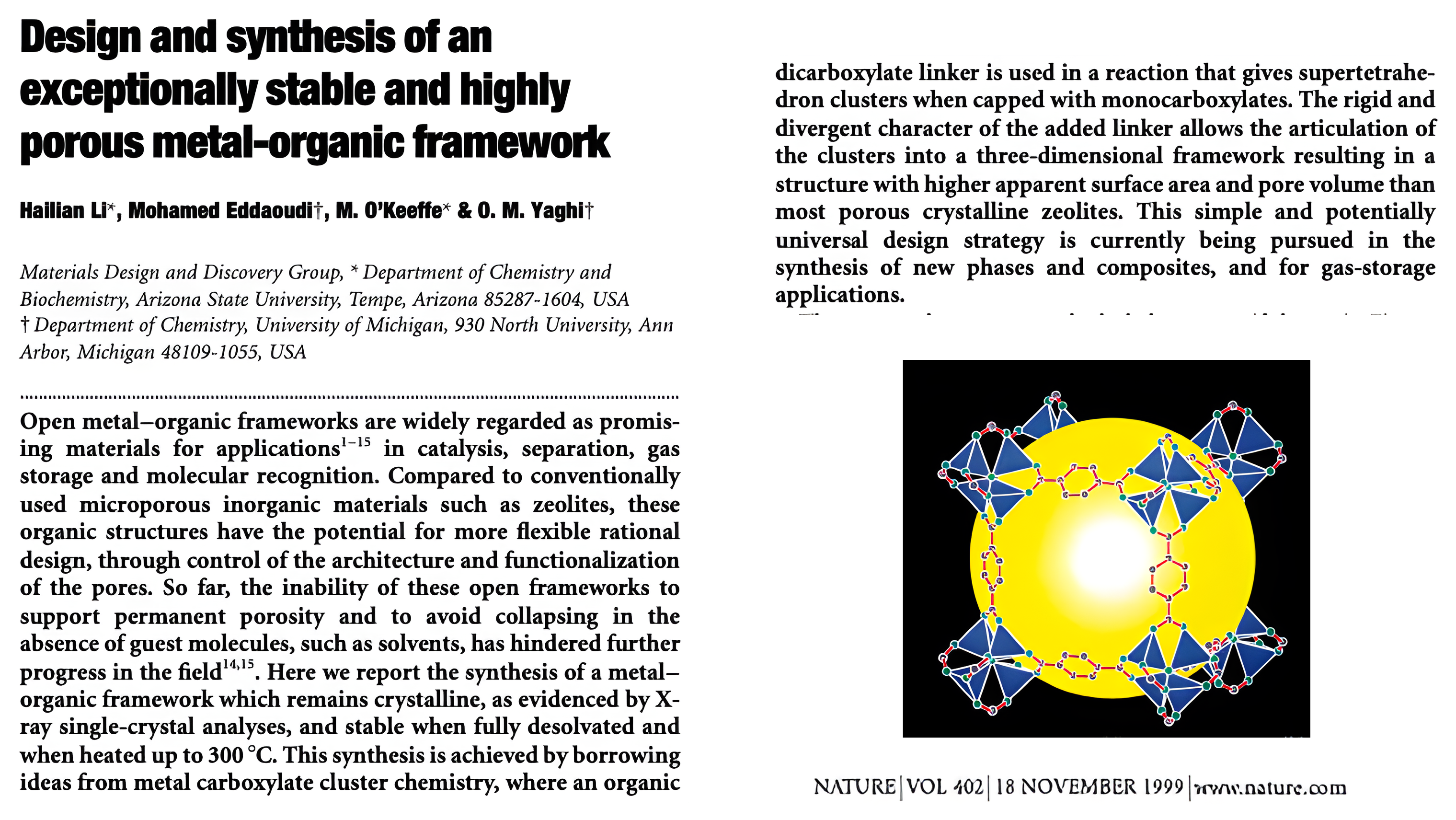
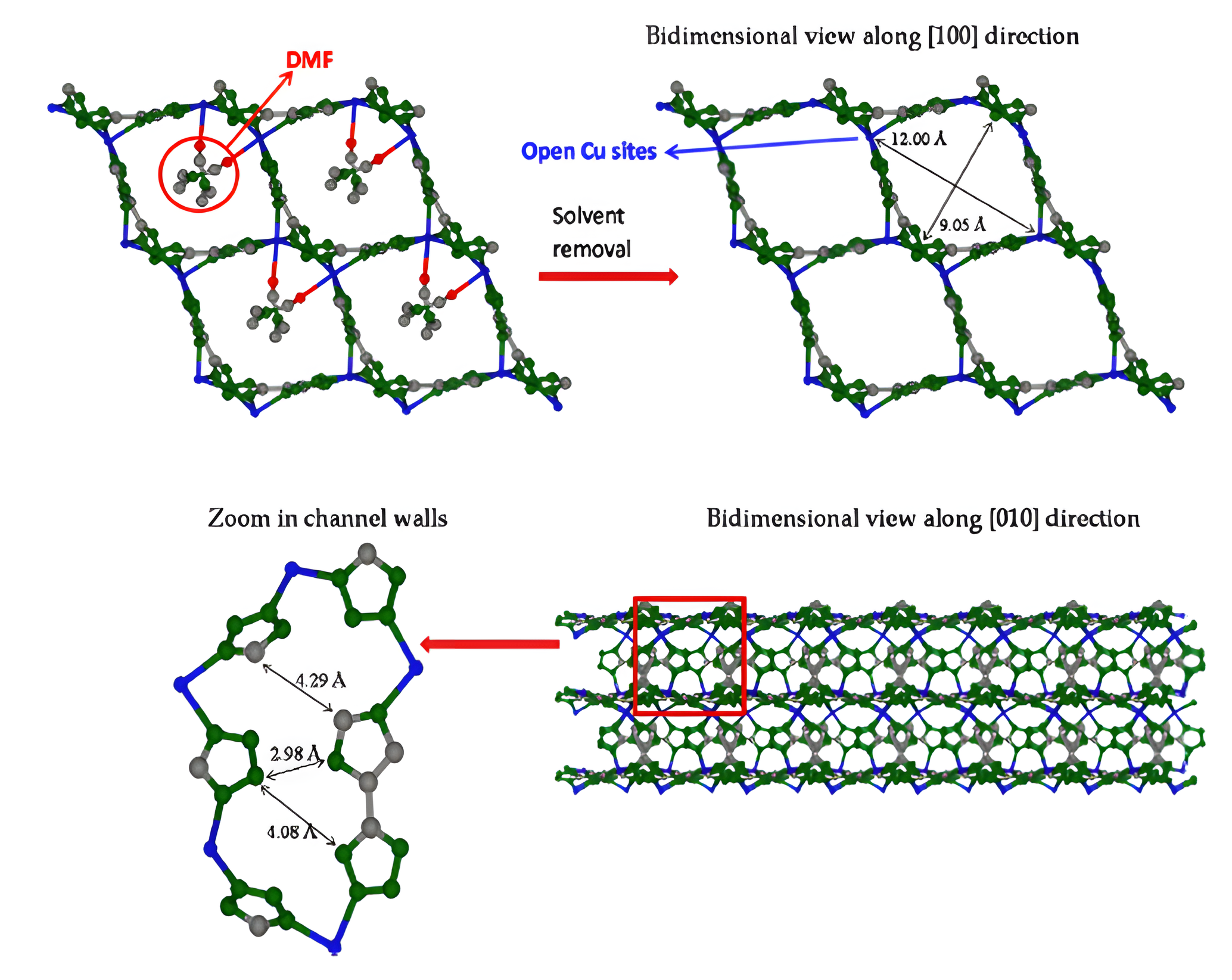
Metal Organic Frameworks (MOFs) = Porous coordination polymers made up of clusters of metal ions or clusters connected by multidentate polyatomic ligands.
ION-X: the status quo problem
1. The status quo problem
- Ion-implant tools in chip fabs need toxic dopant gases: arsine (AsH₃), phosphine (PH₃), BF₃, etc.
- Traditionally stored in high-pressure steel cylinders (pressures often >100 psig).
- Hazards:
- Catastrophic leak risk → a single bottle contains enough toxic gas to endanger workers and trigger fab-wide shutdowns.
- Regulatory & insurance burden → fabs need redundant ventilation, scrubbing, and emergency protocols, raising costs.
- Cylinder heel (unused residual gas) → waste that still poses disposal risks.
2. What the MOF cylinder changes
- MOFs adsorb and store the gas inside their pores, allowing the cylinder to hold the same usable inventory at sub-atmospheric pressure (near vacuum to ~1 atm).
- On use, the gas desorbs in a controlled way to feed the ion-implant tool.
ION-X: why fabs pay for it
3. Why fabs pay for this
- Massively reduced safety risk: Even if the cylinder is breached, no pressurized toxic gas rushes out. That alone cuts the probability and severity of a catastrophic event.
- Regulatory relief: Lower safety classification than high-pressure bottles → lower facility cost, easier permitting, fewer insurance penalties.
- Operational continuity: Prevents fab shutdowns due to leaks or alarms, which are extremely expensive (>$1M/day lost production).
- Waste reduction: Lower “heel” volumes mean less toxic waste to manage and dispose of.
- Compatibility: ION-X cylinders plug directly into existing ion-implant tools (no redesign needed).
4. The value proposition in one line
They convert a toxic-gas supply chain from a high-pressure hazard into a sub-atmospheric, “fail-safe” consumable, saving fabs money on risk, compliance, and downtime.
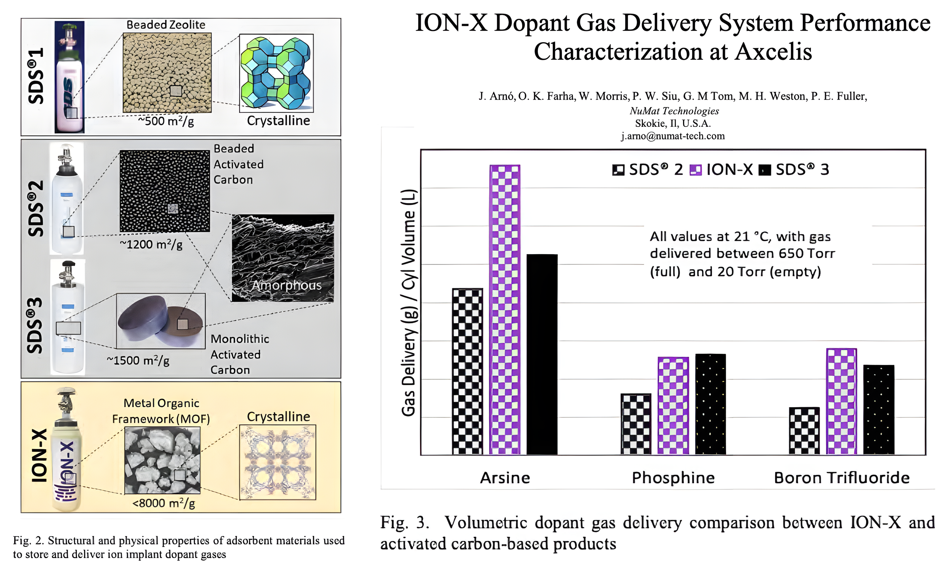
ION-X (MOF) vs SDS (Carbon) Cylinders
| Metric | ION-X (MOF) | SDS (Carbon) |
|---|---|---|
| Gas delivered | Higher usable capacity (20–50% more for some gases) | Lower deliverable, larger residual heel |
| Flow stability | Stable delivery down to very low pressures (few Torr) | Delivery falls off sooner; larger heel |
| Residual gas (heel) | Very low; most gas is recoverable | Higher heel, more waste |
| Purity / contamination | Low metals, stable across cycles | Acceptable, but batch variability possible |
| Reproducibility | Highly consistent (crystalline pores) | More variability (heterogeneous carbon) |
| Safety | Sub-atmospheric storage | Also sub-atmospheric storage (same safety principle) |
Summary
- Silicates dominate Earth’s crust; their tetrahedral networks are defined by O:Si ratios.
- Structural motifs range from isolated tetrahedra to 1D chains, 2D sheets, and 3D frameworks.
- Zeolites are Al/Si tetrahedral frameworks; charge-balancing cations generate accessible pores.
- Key zeolites (sodalite, zeolite A, faujasite) differ in connectivity and pore size (4–7.4 Å).
- Porous materials are classified as microporous (<2 nm), mesoporous (2–50 nm), macroporous (>50 nm).
- MOFs (e.g., MOF-5) extend these ideas: metal–oxide clusters linked by organic ligands create highly porous, tunable frameworks.
Homework
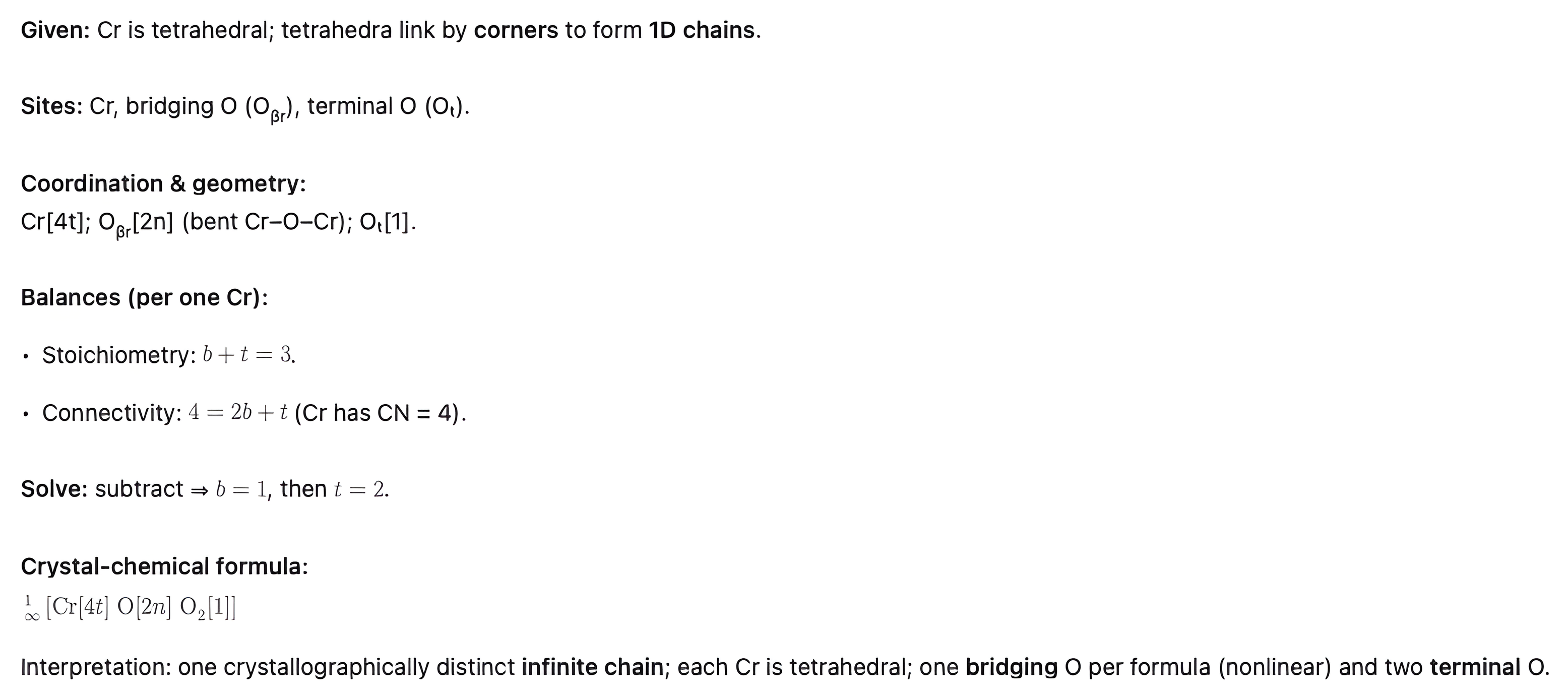
1.22 Write the Niggli formula and the simple crystal-chemical formula for the CrO₃ structure that contains chains of corner-sharing chromium-centered tetrahedra.
1.23 Construct a bond graph or Niggli formula to determine if it is possible for all anions to be equivalent in a structure of tetrahedrally coordinated cations and stoichiometry of C₂A₃? Which alternative Niggli formula complies best with the rule of parsimony?
1.24 Using the Niggli formula and the rule of parsimony, determine the stoichiometry that results from sharing (a) all corners, (b) all edges, and (c) all faces of a cation-centered cube of anions. Note the structure prototype where you recognize it.
1.25 Write the Niggli formula for C₃N₄ made of identical CN₄ tetrahedra. How many different types of nitrogen vertices are there? What is the coordination number of each?
1.26 In β-Li₃N, nitrogen is 11-coordinated. Write down the Niggli formula of the NLi₃ polyhedron.
1.22
Corner sharing tetrahedra in 1‑D chains -> CrO₄ tetrahedra
What the Niggli formula describes
- It’s a connectivity-based formula for one polyhedron (e.g., a tetrahedron or octahedron around a cation).
- It tells you how many anion vertices there are, and how many other polyhedra each vertex connects to.
- You always write it per one cation-centered polyhedron.
- C A(numerator/denominator + numerator/denominator …)
Niggli formula: CrO₂/₂+₂/₁
Silicate tetrahedron SiO₄⁴⁻: oxygen and silicon labelled, above “1. Single Chain”
Crystal-Chemical Formula Algorithm
1. List atoms: Write down each unique cation and anion site.
2. Tag cations: Add coordination number (how many neighbors) + geometry (t = tetra, o = octa, etc.).
3. Tag anions: Mark how many cations each anion connects to: O[1] = terminal, O[2] = bridging, O[3] = 3-connected, etc.
4. Check balances:
- Bonds from cations = bonds accepted by anions.
- Count anions = formula stoichiometry.
- Charges must cancel.
5. Keep it simple: Only include distinct sites/connectivities needed to show bonding.
Practice questions
Work the Lecture 6 practice questions before the next class. They cover network vocabulary, uninodal and binodal nets, silicates and the Niggli formula, zeolites and pore size, and metal-organic frameworks.
Open the Lecture 6 practice questions
Every question carries a worked explanation, so you can check your reasoning as you go.